The Easy Z80 is a neat little 100mm x 100mm RomWBW-compatible Z80 computer with a good set of peripherals that make it perfect for quick test builds and hacks. It includes:
- Z80 CPU (10MHz)
- Z80 CTC
- Z80 SIO/0 (with dual RS-232 level COM ports)
- 512KB ROM
- 512KB RAM
- Memory paging
- SPLD for easy reconfiguration of the I/O mapping of the on-board peripherals
- Power/Reset monitor
- Battery-backed SRAM
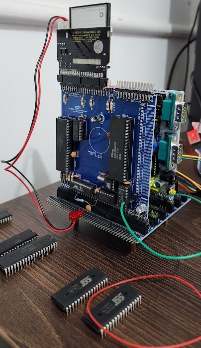
Still, a few additions would make it even more desirable, so I decided to make a new board in the same form factor. This is also the first board I’ve routed, so it’s ugly but thankfully the first prototype worked! They look great stacked and my idea is to create a vertical backplane to house them in a case.
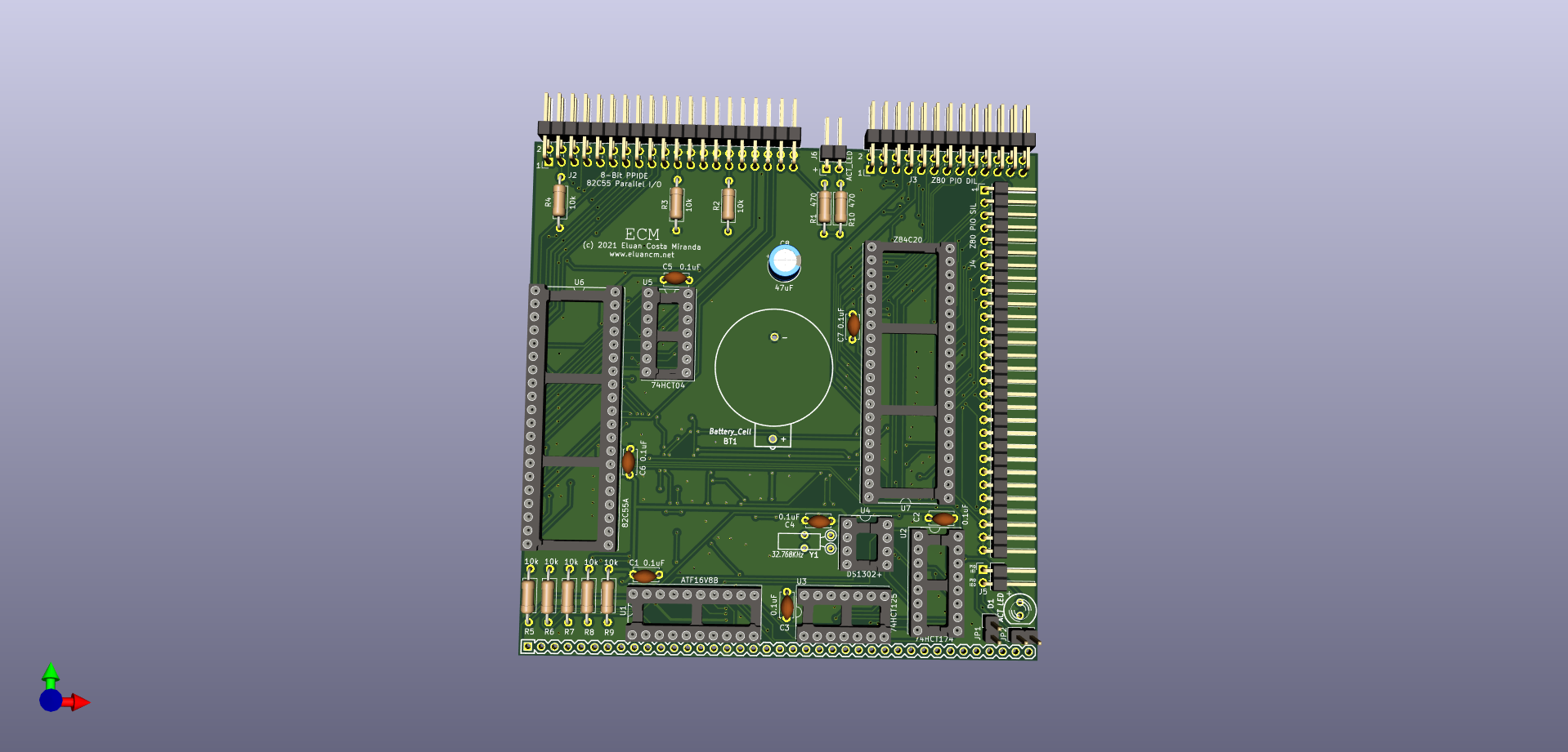
For the lack of a better name, I named the working directory of this project “Easy Z80 Essentials”. It includes:
- PPIDE (8255-based) interface for Hard Disks (plus CF cards and SD cards through adapters).
- DS1302 real time clock.
- Z80 PIO for GPIO and to allow the creation of other peripherals like keyboards, for example.
- Address decode through a SPLD, just like the Easy Z80. They are fully decoded and easily remapped.
To avoid reinventing the wheel, I based this design on the work of others:
I’m thankful for all of their contributions to open source vintage hardware!
Documentation
I/O Memory Map
All of the address below are fully decoded through the SPLD. They sit at the standard locations expected by RomWBW.
| Peripheral | Address |
| RTC | 0xC0 |
| PPIDE | 0x20-0x23 |
| Z80 PIO | 0x68-0x6B |
Connection instructions
| Connector | Notes |
| J1 | Bus connector. |
| J2 | IDE connector. Connect your cable/adapter here. Be aware that, depending on your accessories, you may have to remove pin 20 from this connector before installing it. |
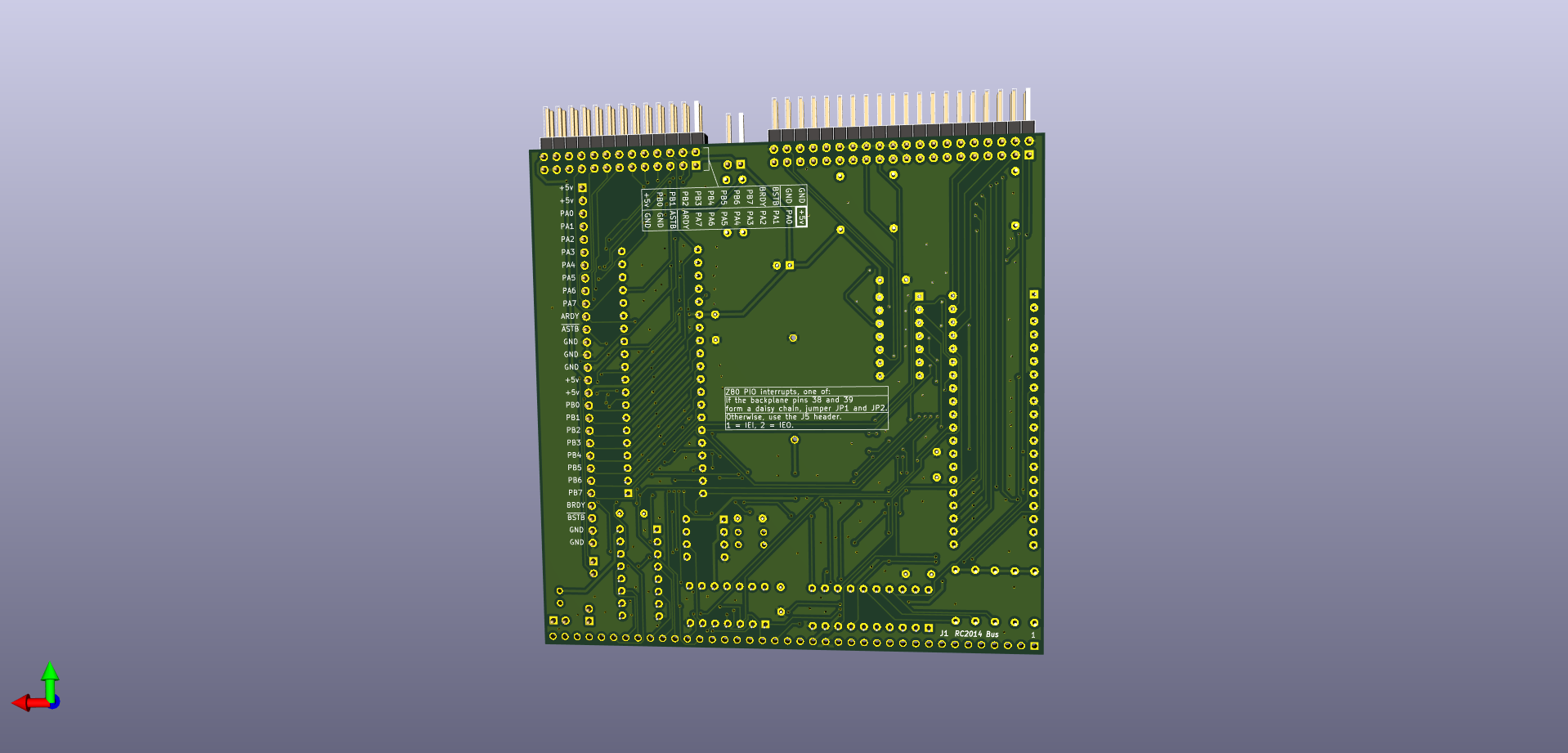
| J3 | Dual-in-line connector for the Z80 PIO signals. Pinout in the silkscreen. |
| J4 | Single-in-line connector for the Z80 PIO signals. Pinout in the silkscreen |
| J5, JP1, JP2 | Z80 Interrupt mode 2 connectors for the Z80 PIO. If your backplane has pins 38 as IEI and pin 39 as IEO forming a daisy-chain, jumper JP1 and JP2. Otherwise use J2 to route IEI and IEO. Pinout in the silkscreen. Do not use both options at the same time! |
| J6 | Optional IDE activity LED cable. One is already included onboard (reference D1). |
| BT1 | Insert a 3V CR2032 battery cell. Be aware of the DS1302 trickle charge setting in RomWBW. |
RomWBW Options
The relevant RomWBW build options should already be set for the EZZ80_std config. They are:
- RTCIO
- PPIDE*
Versions newer than 3.0.1 should also have a PIOENABLE config that, as of 2022-01-10, just detects and initializes the PIO, nothing else.
Files
Bill of Materials
For the 74xx logic ICs, families other than HCT may work. Non-CMOS families like LS will draw more power.
For the 8255 and Z80 PIO, NMOS versions will also work but will also draw much more power. Beware of remarkings of NMOS as CMOS.
The schematic is simple, so it should be trivial to decide what to install depending on what functions you want.
| Type | Reference | Description | Quantity | Suggestion/Notes |
| PCB | – | Easy Z80 Essentials Rev 1 | 1 | For now, download the gerbers and use one of the low-cost PCB houses. |
| IC | U1 | ATF16V8B DIP-20 SPLD | 1 | Mouser 556-AF16V8B15PU Need to program with the file provided in the documentation. |
| IC | U2 | 74HCT174 DIP-16 Hex Flip-Flops W/ Reset | 1 | Mouser 595-CD74HCT174E |
| IC | U3 | 74HCT125 DIP-14 Tri-State Quad Driver | 1 | Mouser 595-SN74HCT125N |
| IC | U4 | DS1302+ DIP-8 RTC | 1 | Mouser 700-DS1302 |
| IC | U5 | 74HCT04 DIP-14 Hex Inverters | 1 | Mouser 595-SN74HCT04N |
| IC | U6 | 82C55A DIP-40 | 1 | New ones from Intersil/Renesas are expensive from reputable sources, try eBay and be aware of fakes and remarkings. |
| IC | U7 | Z80 PIO DIP-40, CMOS, Z84C20xxPEG | 1 | Mouser 692-Z84C2010PEG 10 MHz recommended (the default Easy Z80 clock speed). |
| Resistor | R1, R10 | 470 Ohm, through hole | 2 | Mouser 603-MFR-25FBF52-470R |
| Resistor | R2-R9 | 10K Ohm, through hole | 8 | Mouser 603-MFR-25FRF5210K |
| Capacitor | C1-C7 | 0.1 uF MLCC, 5mm, through hole | 7 | Mouser 594-K104K15X7RF53H5 |
| Capacitor | C8 | 47 uF Aluminum Polymer, 2.5mm, through hole | 1 | Mouser 80-A750EK476M1EAAE40 Should work fine with values down to 10 uF or less. Electrolytic capacitors are also fine. |
| Led | D1 | 5mm (T-1 3/4) LED | 1 | Any regular 5mm (T-1 3/4) LED will be enough. R1 in series to 5V. |
| Crystal | Y1 | 32.768 KHz, 6pF | 1 | Mouser 815-AB26T32768KHZ6B |
| Battery Holder | BT1 | Holder for CR2032 3V Cell, 20mm | 1 | Mouser 122-2420-GR |
| Connector | J1 | 1×39 Pin Header, 2.54mm, Horizontal | 1 | Break up any regular 1×40 2.54mm angled connector |
| Connector | J2 | IDE PCB connector | 1 | Mouser 517-30340-5002 (Angled.) Mouser 517-30340-6002 (Straight, won’t be able to sit below the Easy Z80 depending on the cable/adapter.) You can also break up any regular 2×40 2.54mm straight/angled connector if you have stock. |
| Connector | J3 | 2×13 Pin Header, 2.54mm, Horizontal | 1 | Break up any regular 2×40 2.54mm angled connector |
| Connector | J4 | 1×29 Pin Header, 2.54mm, Horizontal | 1 | Break up any regular 1×40 2.54mm angled connector |
| Connector | JP1-JP2, J5 | 1×02 Pin Header, 2.54mm, Vertical | 3 | Mouser 649-68002-102HLF You can also break up any regular 1×40 2.54mm straight connector if you have stock. |
| Connector | J6 | 1×02 Pin Header, 2.54mm, Horizontal | 1 | Mouser 649-77315-118-02LF You can also break up any regular 1×40 2.54mm angled connector if you have stock. |
| Socket | U4 | DIP-8 7.62mm | 1 | Mouser 517-4808-3000-CP |
| Socket | U3, U5 | DIP-14 7.62mm | 2 | Mouser 517-4814-3000-CP |
| Socket | U2 | DIP-16 7.62mm | 1 | Mouser 517-4816-3000-CP |
| Socket | U1 | DIP-20 7.62mm | 1 | Mouser 517-4820-3000-CP |
| Socket | U6, U7 | DIP-40 15.24mm | 2 | Mouser 517-4840-6000-CP |
To-do List
Silkscreen
- Add board name + revision number (also use the rev field in the schematic).
- Add KiCad, license, do not throw away (WEEE) logos.
- Create a logo + copyright + website link footprint for myself.
- Battery holder: text should be “CR2032 3V”.
- Add text to the silkscreen to remind the user that trickle-charge should be off for the DS1302 since most batteries are not rechargable.
- Add note to remove IDE pin 20 if desired, it’s a key pin in some cables.
PCB
- Re-route, it was amateurish at best.
- Rounded borders.
- Add 2-pin header for battery like the Easy z80 (bonus: add two to chain the SRAM battery from the Easy Z80).
- Add 2-pin header with 5V for low-power CF cards. Also add a jumper to supply 5V through pin 20 if it wasn’t removed.
- IEI-IEO (INT_CHAIN) header from the PIO should be vertical, not face the back panel like the silk screen indicates? (for creating a case that fits into the back of the boards).
- Signals routed below a specific area of the DS1302 can influence the RTC, re-route.
- For the Z80 PIO, also use a connector with two rows for the back of the board, creating space for a second IDE connector for an “external” drive.
Check
- Can the IDE Act signal (IDE pin 39) drive two leds?
History
Rev 1 (2021-04-30)
- First Version